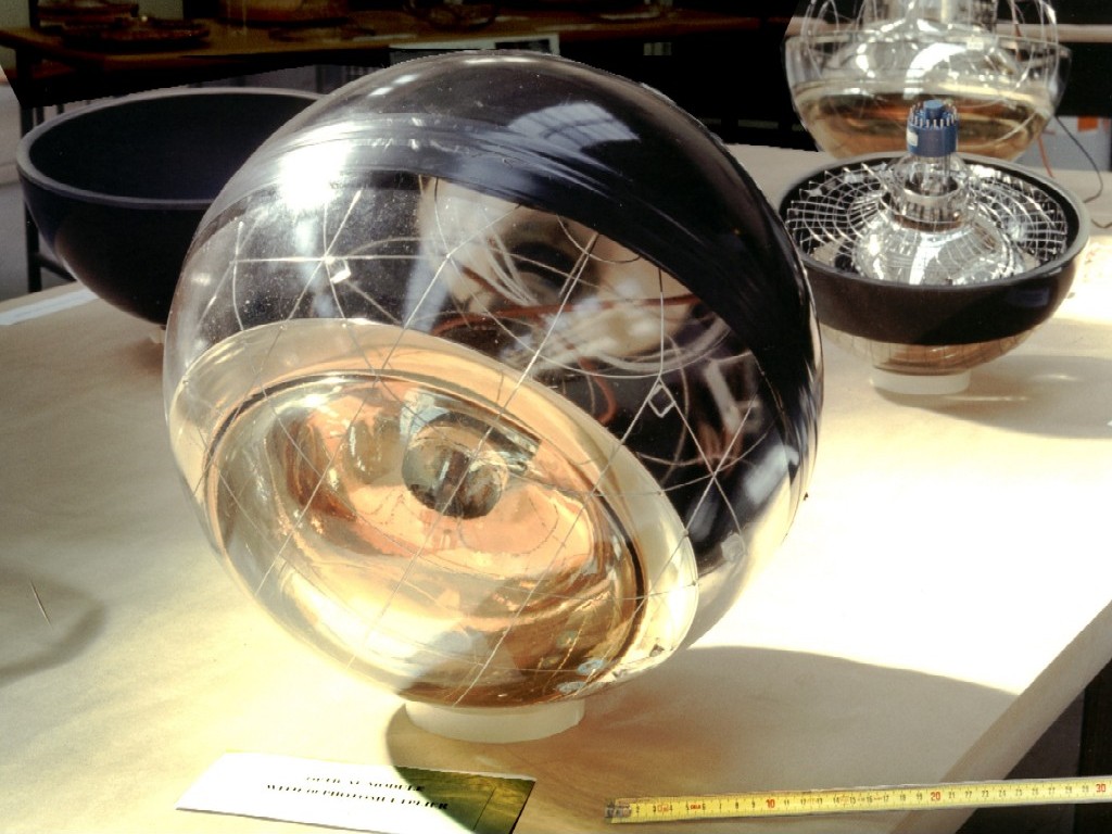
The basic element of the ANTARES detector is the optical module. These optical modules are the eyes of the detector. Each of them consists of a pressure resistant glass sphere hosting a 10-inch photomultiplier. Photomultipliers are able to detect very faint light flashes – even a single photon can be detected – with a temporal precision of about 1 nanosecond.
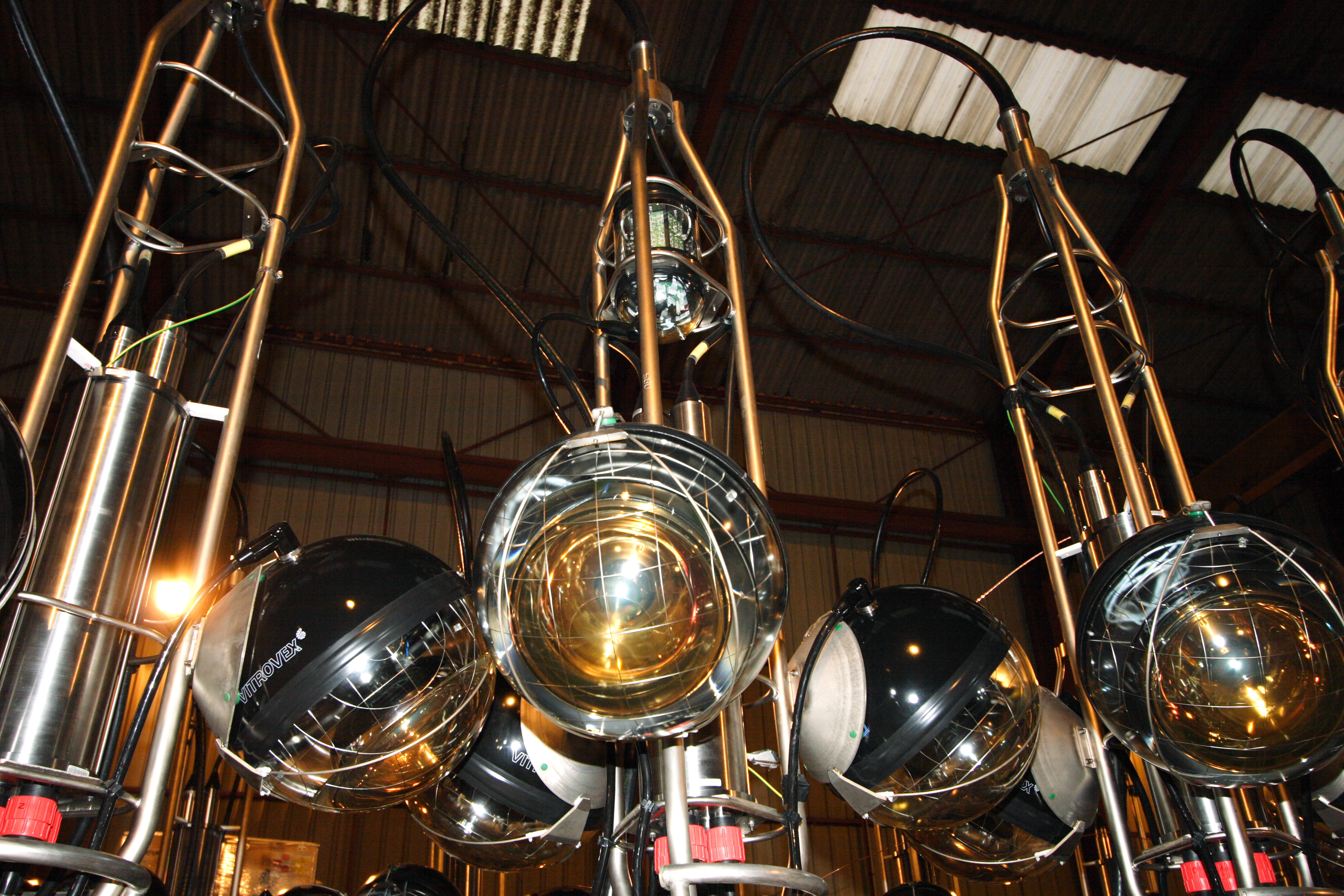
Three such optical modules are grouped in a storey comprising a titanium frame and the optical modules. They are arranged with the axis of the photomultiplier tubes \(45^\circ\) below the horizon. This allows to detect light in the lower hemisphere with high efficiency. There is also an overlap in angular acceptance between adjacent optical modules, permitting to detect coincident photons from the same origin. Three complete storeys, ready for deployment, can be seen below. The central one hosts additionally a LED beacon which can emit very short and well controlled light flashes. Other storeys are equipped with a hydrophone to detect the pings from the acoustic positioning system.
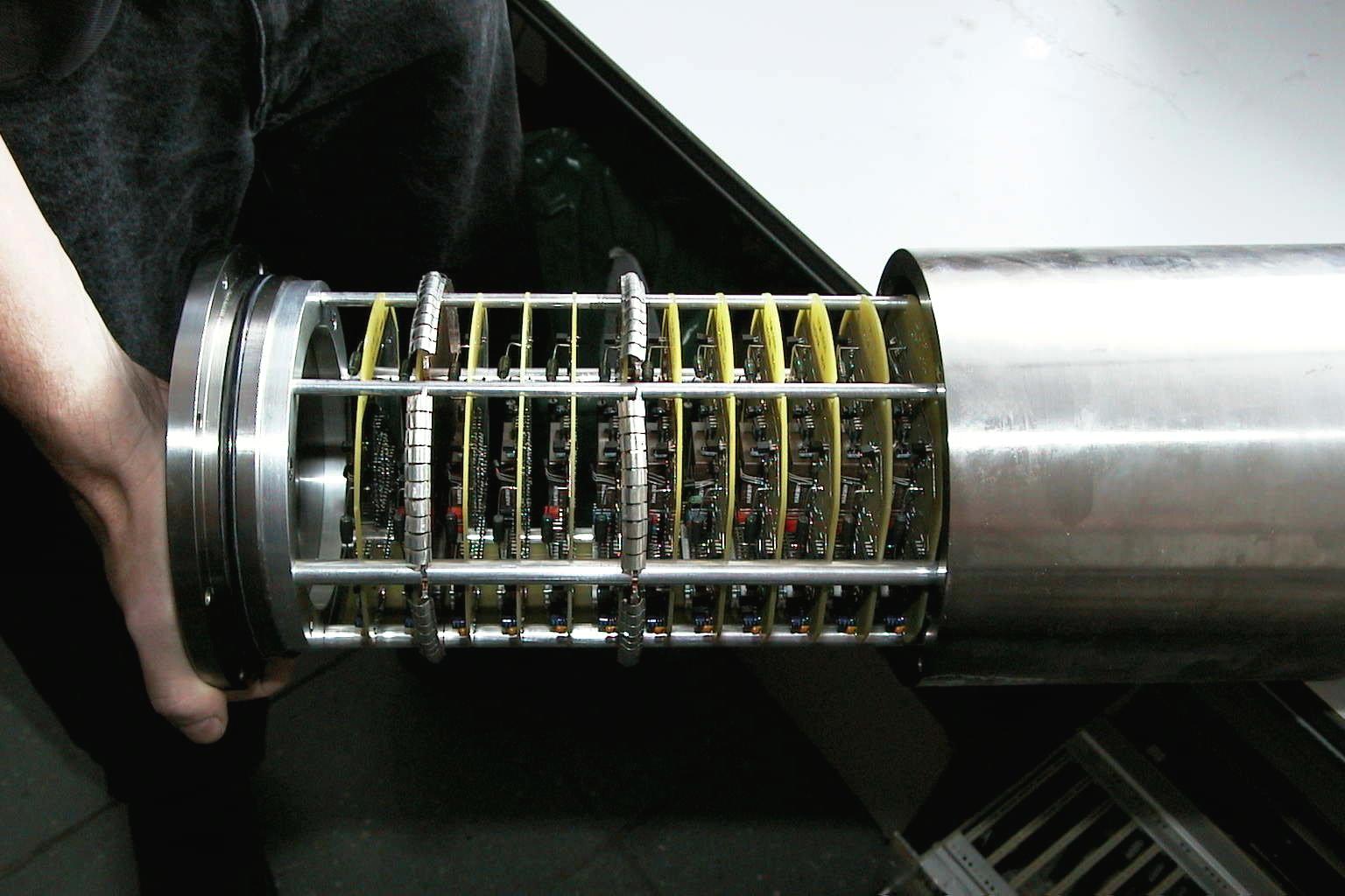
The storey is completed by a central titanium container, called local control module which hosts the data acquisition electronics. This comprises electronic cards which digitize the analogue signals from the optical modules, a compass card to monitor the orientation of the storey, a clock card for time synchronization to better than a nanosecond and occasionally cards to operate calibration devices.
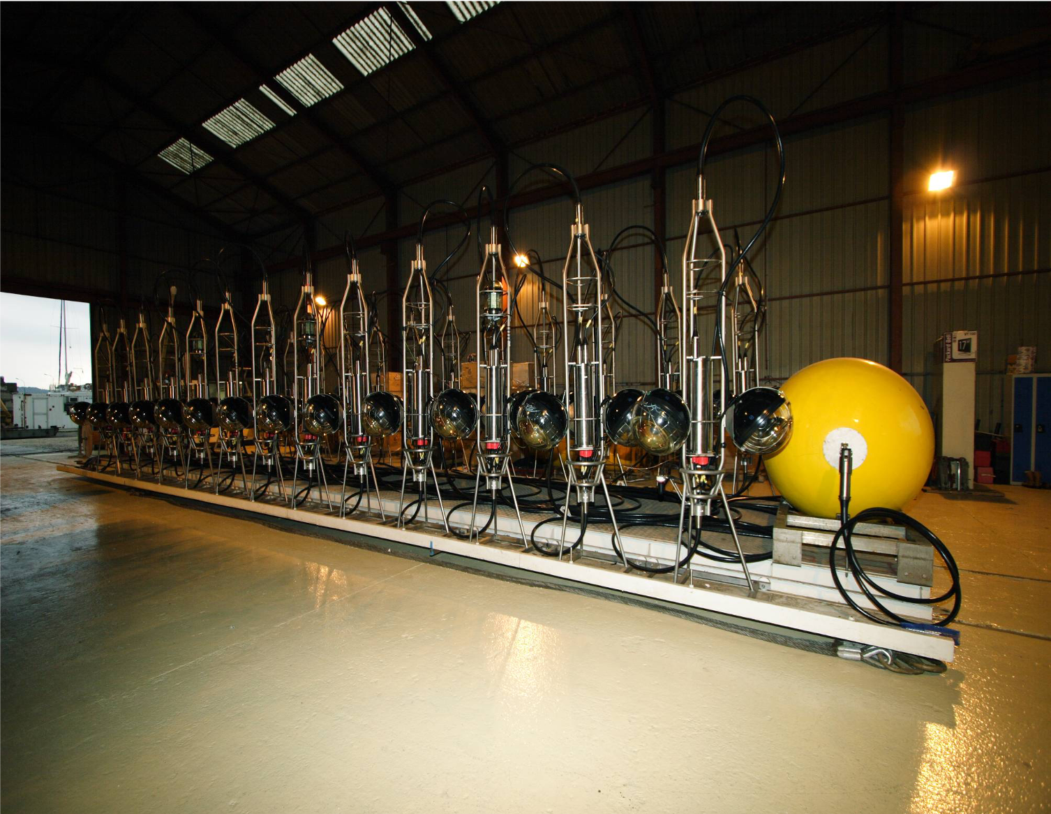
A detector line is composed of 25 storeys aligned with a vertical spacing of 14.5m. The first storey sits at about 100m above the sea bottom, the last one at about 450m. An anchor, equipped with the power supply for the whole line and the data submission equipment keeps the line in place while a buoy at the top keeps it taut. The image shows the first detector line ready for deployment in February 2006.
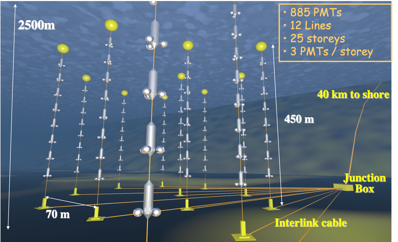
The ANTARES detector consisted of 12 detector lines in an octagonal arrangement with a total of 300 storeys and 885 optical modules. It was installed at a depth of 2500m close to Toulon. The figure below shows a schematic view of the detector array.
