
Nearly a thousand light sensors made up ANTARES, whose calibration is crucial for a successful detection of neutrino events. This goes from time to positioning calibrations, plus monitoring and readjusting of the photomultipliers’ (PMTs) performances, for which a variety of methods and tools were used.
Time Calibration
The ANTARES neutrino telescope detects nearly light speed events along hundreds of meters with an equally extensive array of sensors, making relevant the propagation time of the different signals. Time accuracy of the components becomes therefore critical for a correct estimation of the passing particles and therefore their direction of origin. This is achieved in multiple steps via time calibration of the sensors’ clocks.
A first calibration of the signal propagation paths along the ANTARES lines is done previously to the deployment, where relative corrections within each line are measured with a laser illuminating simultaneously all the PMTs of the line, the so-called dark room calibration. This is completed by a rough estimation in situ of the relative difference between the lines by measuring the roundtrip time of the clock signal with the electronics on the base of each line.
However, many factors can introduce variations to these corrections that require to be monitored and readjusted in situ and over time. For this purpose, a set of controlled light sources, known as Optical Beacons (OB), were integrated within the detector. They came in two kinds:
- Laser OBs were placed on some line bases, powerful enough to illuminate simultaneously sections of all the detector lines.
- 4 LED OBs per line were placed on some floors, which allowed the calibration by sections of the line.
These means allowed a promptly estimation of the new time offsets after deployments, line connections or high voltage tunings. They also provided means for optical properties monitoring and some were prototype tests for the next generation neutrino telescope KM3NeT.

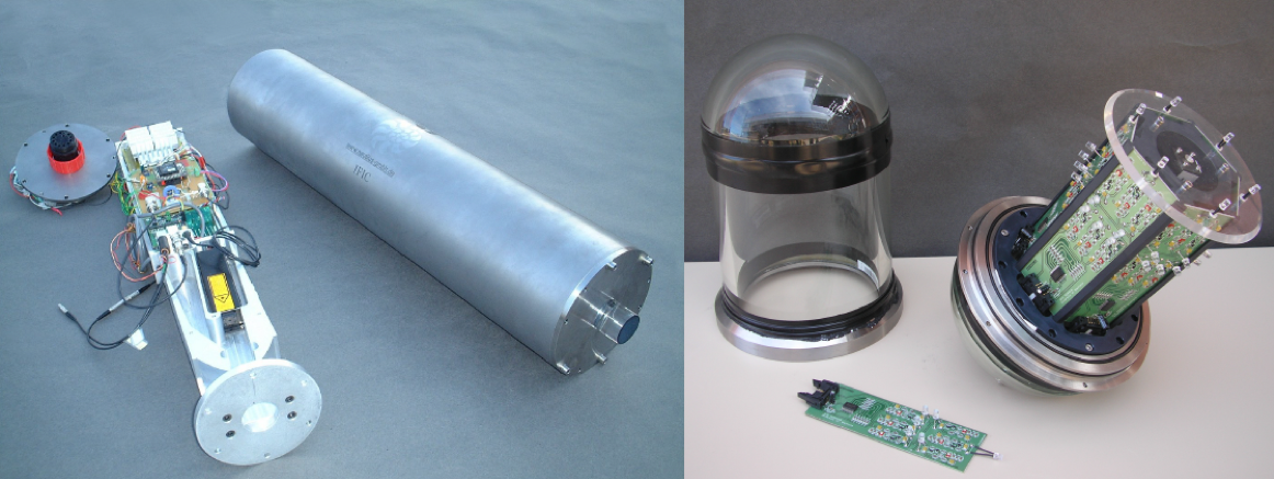
Left: some ANTARES storeys set up for the dark room calibration, a LED OB is visible in the upper part of the storey most to the left. Center: the laser OB. Right: the LED OB.
In addition, when sufficient data was gathered, two techniques for fine adjustments were possible:
- ⁴⁰K calibration: the beta decays of the abundant ⁴⁰K potassium isotope in sea salt, which can illuminate simultaneously nearby optical modules, allow to check the relative time differences between contiguous PMTs within the same floor.
- muon calibration: muons originating from cosmic ray interactions in the atmosphere reach continuously ANTARES depths. These are an abundant source of events, which time residuals, relative to their reconstructed tracks, provide a precious evaluation of the time constants of the detector.
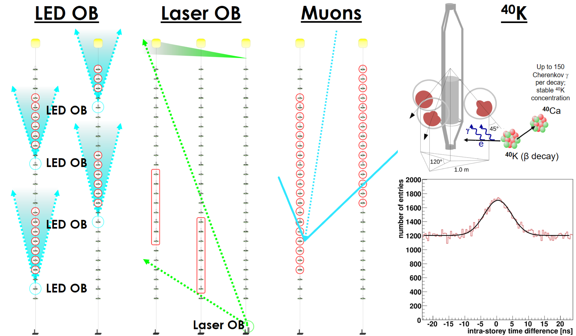
Diagrams of application of the multiple in situ time calibrations of ANTARES.
All these means combined provided the necessary relative time calibration accuracy among the different ANTARES components, allowing a sub-nanosecond average precision in the time assignment of the photons detected by the PMTs. The absolute time precision was determined by GPS technology, of sub-millisecond accuracy, enough for astronomical pointing.
More information:
“Time calibration of the ANTARES neutrino telescope”
Astroparticle Physics Vol. 34, pp. 539–549 (2011)
[doi:10.1016/j.astropartphys.2010.12.004]
“Time calibration with atmospheric muon tracks in the ANTARES neutrino telescope”
Astroparticle Physics Vol. 78, pp. 43–51 (2016)
[doi:10.1016/j.astropartphys.2016.02.001]
Positioning
ANTARES is hosted in a living environment. Its lines are flexible structures anchored to the sea floor and held taut by a buoy. Sea currents cause them constantly to move and their floors to spin. For an accurate reconstruction of particle tracks, it is necessary to have knowledge of the position of the optical modules with an accuracy better than 10 cm.
To know where the ANTARES sensors are at any moment, it counts with an acoustic positioning system, for triangulating distances, and a compass-tiltmeter system, for determining the orientation and inclination of the storeys. The combination of all these inputs are used to infer the position of the many elements of the detector with the necessary precision.
The acoustic positioning system consists of receiving hydrophones on five storeys along each line, as well as emitters on the sea floor around the detector and at the anchor of each line. Travel times of the periodic acoustic signals emitted from the bases to the receivers, once convoluted with the speed of sound at those depths, are combined to triangulate their relative positions.
The compass-tiltmeter system consists of three orthogonal magnetic sensors to measure the Earth magnetic field plus a tiltmeter, both housed on each ANTARES storey. Once properly corrected by each sensor offset, the combination of both measurements allows estimating the absolute orientation of each storey with an accuracy of one degree for the heading angle and 0.2 degrees for the tilts.
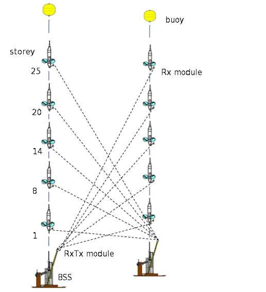

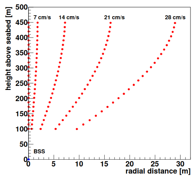
Left: diagram of the acoustic positioning system. Center: horizontal displacements of floors 1 (black), 14 (magenta) and 25 (green) of line 3 from April to June 2011. Right: line shape reconstructions under different sea currents.
The information provided by both systems is combined into a global fit that reconstructs the shape of each line at any time, taking into account dynamical models of the lines. This is completed with acoustic measurements triangulated from ships equipped with GPS on the sea surface at the time of line deployments to obtain the absolute position and orientation of the detector.
More information:
“The positioning system of the ANTARES neutrino telescope”
Journal of Instrumentation Vol. 7, T08002 (2012)
[doi:10.1088/1748-0221/7/08/T08002]
Sensor performance
With the passage of time, the photomultiplier tubes need to readjust their voltages to maintain the nominal signal gain per photon converted in the photocathode. These actions required also to re-estimate the time calibration of each adjusted sensor but such periodic revisions had a positive impact on the photomultiplier performances and were successful in keeping a stable correlation between the integrated charge and the detected photons.
In addition, each one of the “Analogue Ring Samplers” acquisition and signal integration chips in the detector, two per optical module, required of individual calibrations: channel availability on the time-to-voltage converters, photoelectron charge dependance on the analogue-to-voltage converters, and even cross-talk effects.
Moreover, to correctly emulate data taking conditions it is necessary to measure the different sensor capability to detect light and the resulting signal. The frequent beta decays of the potassium isotope ⁴⁰K in the sea water allows the monitoring of the photomultiplier efficiencies, allowing to quantify also the loss of efficiencies along time (due to photocathode aging, biofouling, etc.): at the end of operation, only 80% of efficiency loss was subdued.
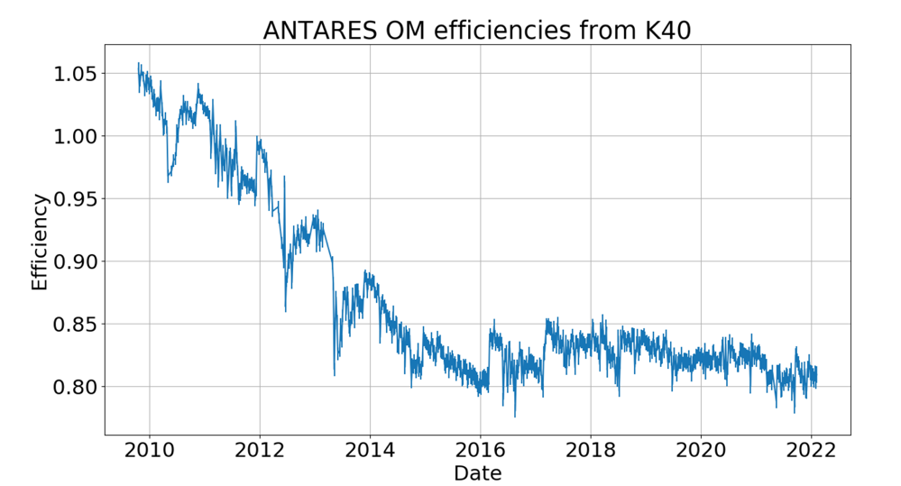
ANTARES ⁴⁰K efficiencies along time. MC estimations assumed a more pessimistic effective area of the photocathodes yielding at the beginning efficiencies slightly above 1, still compatible with the uncertainties derived from the photomultiplier properties (mainly photocathode size and angular acceptance).
More information:
“Long-term monitoring of the ANTARES optical module efficiencies using ⁴⁰K decays in sea water”
The European Physical Journal C Vol. 78:669 (2018)
[doi:10.1140/epjc/s10052-018-6132-2]